- 您现在的位置:买卖IC网 > Sheet目录1996 > HMC700LP4E (Hittite Microwave Corporation)IC FRACT-N PLL 16BIT 24QFN
For price, delivery and to place orders: Hittite Microwave Corporation, 2 Elizabeth Drive, Chelmsford, MA 01824
978-250-3343 tel 978-250-3373 fax Order On-line at www.hittite.com
Application Support: apps@hittite.com
P
LL
-
F
r
a
c
t
io
n
a
L-
n
-
S
M
t
0
0 - 10
HMC700LP4 / 700LP4E
v11.0411
8 GHz 16-Bit Fractional-N PLL
PFD Jitter and Lock Detect Background (Continued)
in summary, the lock detect circuit must not interpret fractional modulation or normal phase noise related jitter as
being out of lock, while at the same time declaring loss of lock when truly out of lock.
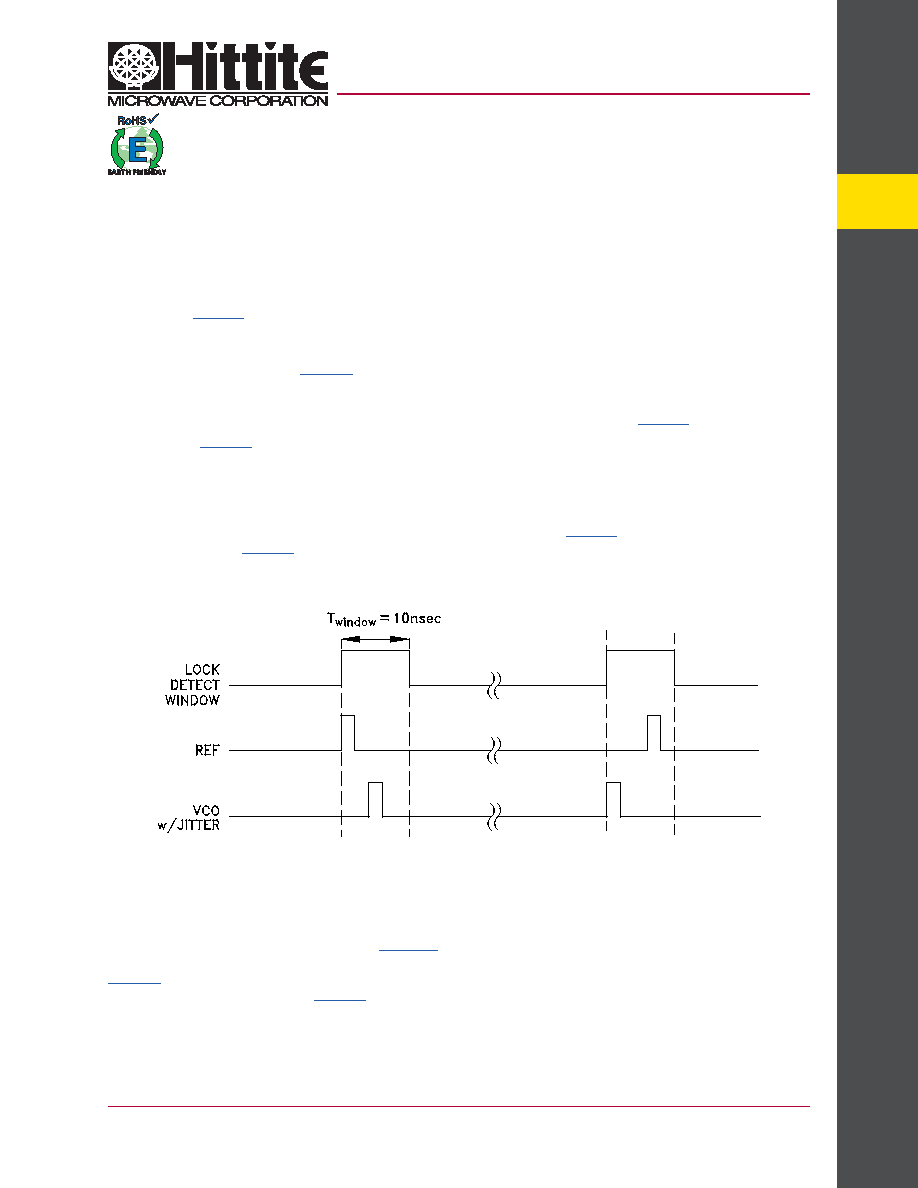
PFD Lock Detect
lkd_enable in table 14 enables the lock detect functions of the HMc700LP4(E).
the Lock Detect circuit in the HMc700LP4(E) places a one shot window around the reference. the one shot window
may be generated by either an analog one shot circuit or a digital one shot based upon an internal ring oscillator.
clearing ringosc_oneshot_sel (table 14) will result in a fixed analog based nominal 10 nsec window, as shown in
Figure 11. Setting ringosc_oneshot_sel will result in a variable length widow based upon a high frequency internal ring
oscillator. the ring oscillator frequency is controlled by ringosc_cfg. the resulting lock detect window period is then
generated by the number of ring oscillator periods defined in oneshot_duration, both in (table 14).
wincnt_max in table 14 defines the number of consecutive counts of the divided Vco that must land inside the lock
detect window to declare lock. if for example we set wincnt_max = 1000 , then the Vco arrival would have to occur
inside the ±10 nsec widow 1000 times in a row to be declared locked, which results in a Lock Detect Flag high. a single
occurrence outside of the window will result in an out of lock, i.e. Lock Detect Flag low. once low, the Lock Detect Flag
will stay low until the wincnt_max =1000 condition is met again.
the Lock Detect Flag is output to LD_SDo pin according to pfd_LD_opEn (table 18) or to the internal SPi read only
register if locked = 1 (table 21). Setting pfd_LD_opEn will display the Lock Detect Flag on LD_SDo except when a
serial port read is requested, in which case the pin reverts temporarily to the Serial Data out pin, and returns to the
Lock Detect Flag after the read is completed. timing of the Lock Detect and Serial Data out functions are shown in
Figure 11.
Figure 11. Normal Lock Detect Window
When operating in fractional mode the linearity of the charge pump and phase detector are much more critical than in
integer mode. the phase detector linearity is worse when operated with zero phase offset. Hence in fractional mode
it is necessary to offset the phase of the PFD reference and the Vco at the phase detector. in such a case, for
example with an offset delay, as shown in Figure 12, the Vco arrival will always occur after the reference. the
lock detect circuit can accommodate a fixed offset delay by setting lkd_win_asym_enable and win_asym_up_sel in
table 14. Similarly the offset can be in advance of the reference by clearing lkd_win_asym_up_sel while leaving
lkd_win_asym_enable set both in table 14. there are certain conditions, such as operating near the supply limits of
the charge pump which make it advantageous to use advanced or delayed phase offset, hence both are available.
发布紧急采购,3分钟左右您将得到回复。
相关PDF资料
HMC703LP4E
IC FRACT-N PLL W/SWEEPR 24QFN
HMC704LP4E
IC FRACT-N PLL 16BIT 24QFN
HMC830LP6GE
IC FRACT-N PLL W/VCO 40QFN
HMP8117CNZ
IC VIDEO DECODER NTSC/PAL 80PQFP
HMP8156ACNZ
IC VIDEO ENCODER NTSC/PAL 64MQFP
HSP45102SC-40Z
IC OSC NCO 40MHZ 28-SOIC
HSP45106JC-33Z
IC OSC NCO 33MHZ 84-PLCC
HSP45116AVC-52Z
IC OSC NCO 52MHZ 160-MQFP
相关代理商/技术参数
HMC700LP4ETR
制造商:Hittite Microwave Corp 功能描述:IC FRACT-N PLL 16BIT 24QFN 制造商:Hittite Microwave Corp 功能描述:HMC700 Series 8 GHz 16-Bit Prescaler Fractional-N PLL - 4x4 mm QFN-24
HMC701LP6C
制造商:HITTITE 制造商全称:Hittite Microwave Corporation 功能描述:8 GHz 16-BIT FRACTIONAL-N SYNTHESIZER
HMC701LP6C_10
制造商:HITTITE 制造商全称:Hittite Microwave Corporation 功能描述:8 GHz 16-BIT FRACTIONAL-N SYNTHESIZER
HMC701LP6CE
制造商:Hittite Microwave Corp 功能描述:IC SYNTHESIZER W/SWEEPER 40-QFN
HMC702LP6CE
制造商:Hittite Microwave Corp 功能描述:IC SYNTHESIZER W/SWEEPER 40-QFN
HMC702LP6CE_10
制造商:HITTITE 制造商全称:Hittite Microwave Corporation 功能描述:14 GHz 16-BIT FRACTIONAL-N SYNTHESIZER
HMC702LP6CE_11
制造商:HITTITE 制造商全称:Hittite Microwave Corporation 功能描述:14 GHz 16-BIT FRACTIONAL-N PLL
HMC703LP4E
功能描述:IC FRACT-N PLL W/SWEEPR 24QFN RoHS:是 类别:集成电路 (IC) >> 时钟/计时 - 时钟发生器,PLL,频率合成器 系列:- 标准包装:2,000 系列:- 类型:PLL 频率合成器 PLL:是 输入:晶体 输出:时钟 电路数:1 比率 - 输入:输出:1:1 差分 - 输入:输出:无/无 频率 - 最大:1GHz 除法器/乘法器:是/无 电源电压:4.5 V ~ 5.5 V 工作温度:-20°C ~ 85°C 安装类型:表面贴装 封装/外壳:16-LSSOP(0.175",4.40mm 宽) 供应商设备封装:16-SSOP 包装:带卷 (TR) 其它名称:NJW1504V-TE1-NDNJW1504V-TE1TR